Network Virtualization
Locator/ID Separation Protocol (LISP)
Locator/ID Separation Protocol (LISP) is a routing architecture that provides new semantics for IP addressing. Basically, our identity is not just an address.
The current IP routing and addressing architecture uses a single numbering space, the IP address, to express two pieces of information:
- Device identity
- The way the device attaches to the network
LISP separates our address into 2 parts: the location and our id
It gives you 5 advantages:
- scale internet routing tables
- multihoming
- mobility
- IPV6 network migartion
- and over-the-top virtualization
The LISP routing architecture design separates the device identity, or endpoint identifier (EID), from its location, or routing locator (RLOC), into two different numbering spaces. including improved routing system scalability, and improved multihoming efficiency and ingress traffic engineering.
These are LISP componets:
- TR (Ingress tunnel router) – receives the packet from local site and encapsulates them to the remote LISP site or natively forwards the packet to a non LISP sites.
- ETR (Egress tunnel router) – receives packet from the core network and de-encapsulates the packet and sends it to site.
- PITR (Proxy ingress tunnel router) – receives packet from non LISP sites and encapsulates the packet to LISP sites or forward them natively.
- PETR (Proxy egress tunnel router) – de-encapsulates packets from LISP sites to deliver them to non LISP sites
- MS (Map server) – is a mapping database which is accepting registration requests from its client egress tunnel routers (ETRs)
- MR (Map resolver) – The function of the LISP MR is to accept encapsulated Map-Request messages from ingress tunnel routers (ITRs), decapsulate those messages, and then forward the messages to the MS responsible for the egress tunnel routers (ETRs) that are authoritative for the requested EIDs.
VXLAN or Virtual Extensible LAN, is a tunneling protocol that allows you to connect two layer 2 segments together over a layer 3 network.
It may not be immediately obvious what the benefits of this are because we're no used to using routing to keep layer 2 domains separate from one another, but this enables us to design some extremely flexible networks. VXLANts highly use in data center
we can easily go over 4000 vlans in a data center, so we need vxlan.
Instead of having a VLAN number, VXLAN uses a VXLAN network identifier (VNI).
VLANs to a maximum of 4,096, due to the 12-bit VLAN tagging method detailed in the standard.With 24-bit VNI field it gives us a maximum of 16 million vxlan.Because VLANs operate at Layer 2, application components cannot be routed to different subnets or across the network.
We’ve heard about Cisco’s three-tier network design where we had the following layers: (1) Access, (2) Distribution, and (3) Core.
The Access Layer connected to our end devices (e.g. clients and servers).
The Distribution Layer redundantly interconnected Access Layer switches, and provided redundant connections to the campus backbone (i.e. the Core Layer).
The Core Layer then provided very fast transport between Distribution Layer switches.
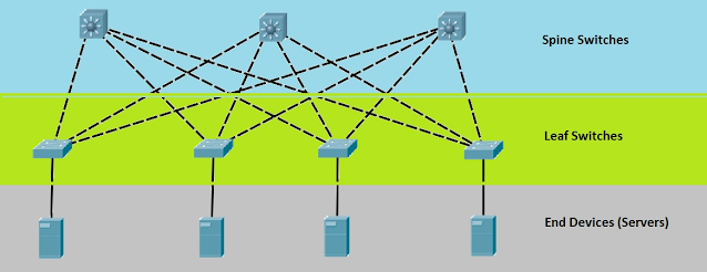
- However, within today’s data centers, a new topological design has taken over. It’s called a Leaf-and-Spine topology
- These switches act as the leaves in a Leaf-and-Spine topology.
- The spine-leaf architecture has become a popular data center architecture, bringing many advantages to the data center, such as scalability, network performance, etc.
- Ports in a leaf switch have one of two responsibilities:
- (1) connecting to a node (e.g. a server in the rack, a firewall, a load-balancing appliance, or a router leaving the data center) or
- (2) connecting to a spine switch.
The spine-leaf architecture consists of only two layers of switches: spine and leaf switches.
The spine layer consists of switches that perform routing and work as the core of the network.
The leaf layer involves access switches that connect to servers, storage devices, and other end-users. This structure helps data center networks reduce hop count and reduce network latency.
- (VEM) can do VXLAN encapsulation ( has at least 1 ip address)
- (VTEP )VXLAN tunnel point : Using an IP address from the VEM.It uses a temporary tunnel to another switch .A layer 3 domain
The VXLAN tunnel endpoint (VTEP) is the device that’s responsible for encapsulating and de-encapsulating layer 2 traffic. This device is the connection between the overlay and the underlay network.
The VTEP comes in two forms:
- Software (host-based) Hypervisors like VMWare’s ESXi or Microsoft’s Hyper-V.
- Hardware (gateway) A hardware VTEP is a router, switch, or firewall which supports VXLAN. We also call a hardware VTEP a VXLAN gateway because it combines a regular VLAN and VXLAN segment into a single layer 2 domain.
Rather than sending each packet multiple times, VTEPs use multicast routing to send each outgoing packet once to reach multiple destinations.
If the destination is on the same subnet, it uses an Address Resolution Protocol (ARP) broadcast message to locate the other component.
The VTEP encapsulates the ARP request in UDP and VXLAN headers, sending the packet to the IP multicast group associated with the VXLAN segment to which the communicating components belong.
Network Virtualization
 Reviewed by ohhhvictor
on
August 24, 2022
Rating:
 Reviewed by ohhhvictor
on
August 24, 2022
Rating:


No comments: